A bore called out as 25 H7 must measure between 25.000 mm and 25.021 mm. A hole that comes off the machine at 25.024 mm fails the callout, even when the shaft slides in smoothly and the surface finish looks perfect. That gap between the limits on a drawing and the feel of parts in a fitter's hand is where most H7 arguments start.
The short answer is that H7 describes neither a tight fit nor a loose fit. It describes one half of a fit: a hole tolerance zone that begins exactly at nominal size and extends upward by an amount set by the nominal diameter alone. Whether the assembly slides, locks or presses depends entirely on the shaft paired with it.
What the H7 code actually tells you
The code carries two pieces of information. The letter H is the fundamental deviation for a hole, and capital letters in the ISO system always refer to internal features while lowercase letters refer to shafts. H sets the lower deviation at zero, so the smallest acceptable hole is the nominal size itself. The number 7 is the tolerance grade that fixes the width of the zone, and ISO 286-1:2010 defines both.
A 25 H7 bore therefore runs from 25.000 mm to 25.021 mm. The same dimension written as 25 h7 describes a shaft sitting entirely below nominal size, from 24.979 mm to 25.000 mm. The two callouts look almost identical on a print and behave in opposite ways.
- The letter sets the position of the zone and the number sets its width. H7 and H8 share a position and differ only in width.
- H7 is always a hole. A shaft can never be H7.
- Both limits of an H7 hole sit at or above nominal size, which is what makes shop floor gauging so simple.
H7 width changes with bore size
IT7 is not a single figure. It steps up with nominal size because machining capability, thermal movement and load effects all scale with diameter: 0.012 mm at a 6 mm bore, 0.040 mm at 150 mm.
H7 hole limits for common ISO 286 size ranges, values in millimetres, referenced to 20 degrees Celsius.
| Nominal size range |
IT7 width |
H7 limits for a typical bore |
| Over 3 up to 6 |
0.012 |
6.000 to 6.012 |
| Over 6 up to 10 |
0.015 |
10.000 to 10.015 |
| Over 10 up to 18 |
0.018 |
18.000 to 18.018 |
| Over 18 up to 30 |
0.021 |
25.000 to 25.021 |
| Over 30 up to 50 |
0.025 |
40.000 to 40.025 |
| Over 50 up to 80 |
0.030 |
60.000 to 60.030 |
| Over 80 up to 120 |
0.035 |
100.000 to 100.035 |
| Over 120 up to 180 |
0.040 |
150.000 to 150.040 |
Two details sit behind those numbers. A size range is a range, so a 19 mm bore and a 30 mm bore share the same 0.021 mm allowance, which makes the smaller bore proportionally looser. Every figure also assumes measurement at a stable 20 degrees Celsius, which is why a bore checked straight after a heavy roughing cut can appear out of tolerance when it is not.
Why H7 is the default hole on drawings
Most designs use the hole basis system, where the hole stays at H and the shaft is adjusted to deliver the required fit. The reason is tooling economics rather than preference. Reamers, boring heads, plug gauges and setting rings are made to nominal size, so a zone that starts at nominal keeps standard tooling in play instead of forcing special orders.
The zero lower deviation also gives one clean rule for the operator: a hole exactly on size is always acceptable. The trade off is that aiming for nominal size leaves nothing for tool wear or shape error, so a better target is the middle of the zone with a monitored trend that warns before the upper limit is reached.
What H7 delivers with different shafts
The shaft decides the character of the fit. At a 25 mm nominal size, where the H7 hole spans 25.000 mm to 25.021 mm, the pairings below show what the assembly actually receives.
Calculated results for a 25 mm H7 hole mated with common ISO 286-1 shaft tolerances.
| Shaft callout |
Shaft limits |
Result at 25 mm |
Typical use |
| h6 |
24.987 to 25.000 |
Clearance 0 to 0.034 mm |
Location fits, dowel pins, easily assembled parts |
| g6 |
24.980 to 24.993 |
Clearance 0.007 to 0.041 mm |
Sliding fits, spigots and covers that must move |
| f7 |
24.959 to 24.980 |
Clearance 0.020 to 0.062 mm |
Running fits, journals, lubrication gaps |
| k6 |
25.002 to 25.015 |
Interference up to 0.015 mm or clearance up to 0.019 mm |
Transition fits and location rings needing light grip |
| p6 |
25.022 to 25.035 |
Interference 0.001 to 0.035 mm |
Light press fits and pins held against rotation |
The h6 row deserves attention. H7 with h6 can reach zero clearance at the limits and can never produce interference, which is why it dominates location work where alignment matters more than grip. Switch to p6 and the same hole becomes a light press fit, with the smallest interference appearing only when both parts land at the extremes of their zones.
H7 where bearings actually sit
Bearing seats are where these numbers stop being academic. An outer ring carries its own tolerance band and its own roundness limits, so a housing bore cannot be judged in isolation. It has to hold the ring without distorting it across the whole operating temperature range.
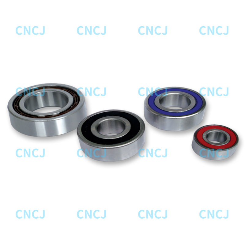
Housing bores for double row angular contact bearings
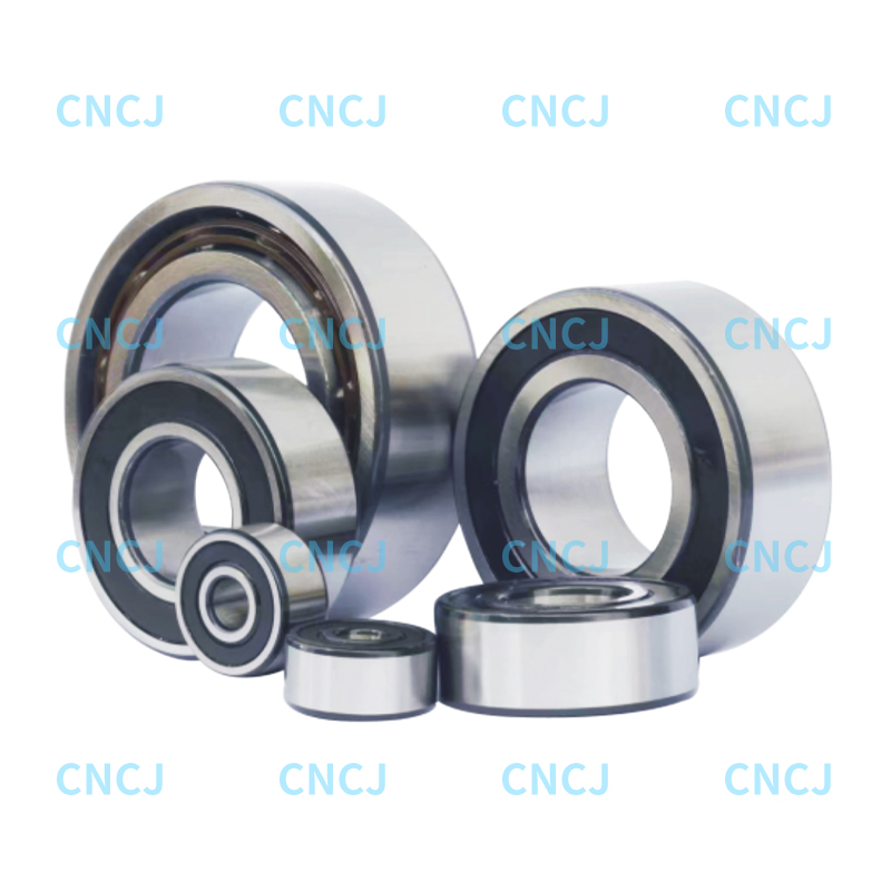
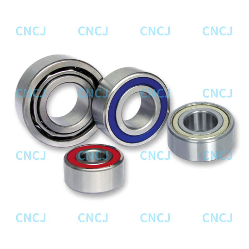
In gearboxes, pumps and compact drives, double row angular contact ball bearings carry combined radial and axial loads in a short axial space. A common arrangement puts the stationary load ring in an H7 housing bore and the rotating inner ring on a k6 or m6 shaft seat. Reverse the load direction so the outer ring rotates and the housing bore usually moves toward J7 or K7, which is why blanket H7 rules produce creeping rings and fretting marks after a few thousand hours.
Seat sizing and bearing choice belong in the same conversation, because preload and clearance targets set the acceptable range. The logic that governs selecting a double row angular contact ball bearing model for a specific application should drive the housing callout, not follow it.
 32, 33 Series Double Row Angular Contact Ball Bearings32, 33 Series Double Row Angular Contact Ball Bearings Princinal Dimensions (mm) Bearing Designations Basic Ratings Maxronoutspeed Mass(kg) d D B r P.NO. Shielded Seal...View Product →
Motor, pump and general machinery seats
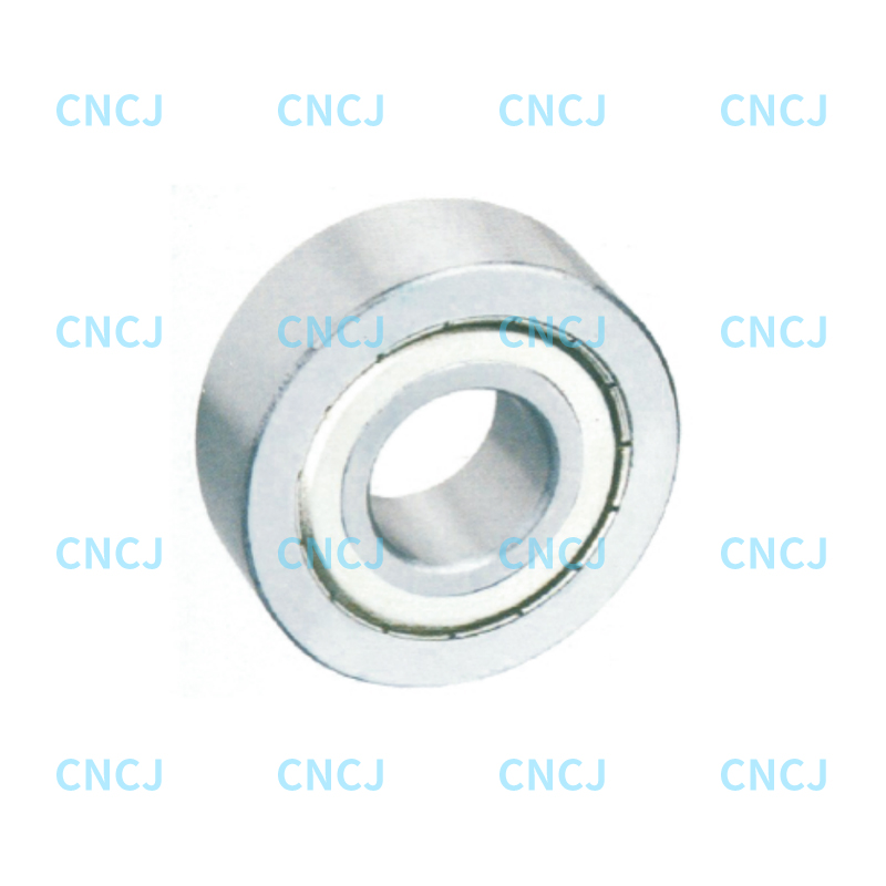
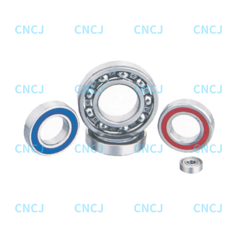
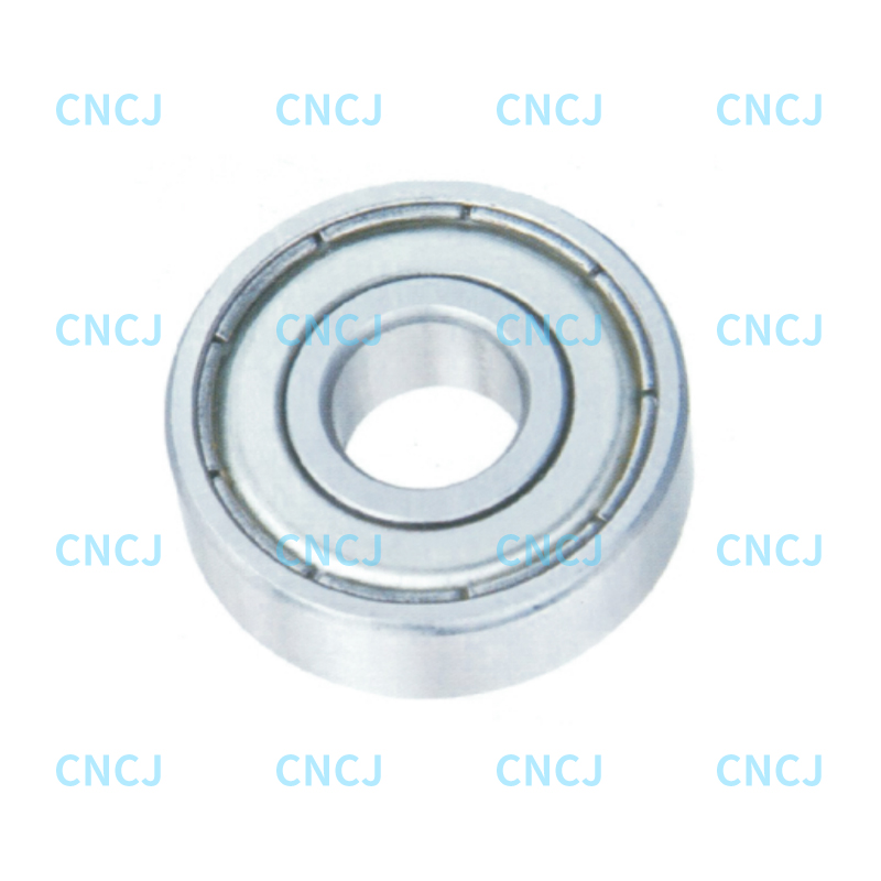
In small electric motors, fans and conveyors, deep groove ball bearings do the work and the housing is again usually H7 or J7 depending on load direction. Because bore and ring tolerances stack, a bore sitting at the top of the H7 zone can reduce effective interference to zero on a nominal ring diameter. That is fine for a stationary load and risky under heavy vibration.
 Deep Groove Ball BearingsRecommended productsView Product →
Verifying an H7 hole without guessing
Three tools cover most checks, and each has a weakness worth knowing.
- Go and no-go plug gauges. The go plug, made to the lower limit, must pass the full bore length, while the no-go plug, made to the upper limit, must not. It is fast and cheap, but it is a two point check, so a three lobed bore can pass both gauges.
- Bore gauges with a setting ring. A dial bore gauge set against a certified ring shows the real size and lets an operator plot a production trend.
- Coordinate measuring machines or a form tester. Only a scanning instrument reveals roundness and cylindricity. A size tolerance is not a form tolerance, and ISO 286 does not limit lobing in a hole unless an envelope requirement or a separate geometric callout applies.
Two habits keep readings honest. Measure at the 20 degrees Celsius reference or apply a correction, since a steel bore grows by roughly 0.012 mm per 10 degrees of change at 100 mm diameter. Also remember ISO 14253-1: a result conforms only when the measured value plus the measurement uncertainty still falls inside the limits, so a bore at 25.020 mm checked with 0.003 mm of uncertainty is not proven acceptable.
Producing H7 reliably
Below roughly 25 mm, drilling followed by reaming is the usual route, and the finished size depends on reamer diameter, cutting fluid, feed rate and how many holes the reamer has already cut. Reamers wear fastest in the first few hundred holes, so sampling frequency matters more than the nominal reamer size printed on the tool label.
Larger bores are turned or bored and finished with a light low feed pass. Tool nose radius, spindle growth and workpiece deflection all move the result, and a boring bar with long overhang cuts a tapered hole rather than a straight one. Deburring both ends is not cosmetic either, because a raised edge reads as undersize on a plug gauge and stops a bearing from seating squarely.
Mistakes that cost money
- Writing h7 where H7 is meant. A hole and a shaft with the same letter and grade are not the same feature, and the error often survives until the first parts are inspected.
- Assuming one tolerance value for all sizes. The 0.021 mm allowance at 25 mm is not valid at 100 mm, where IT7 is 0.035 mm.
- Specifying H7 where H8 or H9 would do. Every step up in grade adds reaming passes, gauging time and scrap cost with no benefit on a non critical cover or bracket.
- Calling out a hole tolerance without a mating shaft tolerance, which leaves the fit undefined and the assembly result to chance.
- Treating the size tolerance as control of shape. Out of round bores pass two point gauging and still distort the ring sitting in them.
- Ignoring temperature during measurement, the most common reason two inspectors disagree about the same bore.
Bringing it back to the drawing
H7 is a hole zone with its lower limit at nominal size and a width taken from the size range, and it says nothing about how tight the assembly will feel. Decide the fit first, then write both halves of it, because an H7 hole paired with h6, g6, k6 or p6 produces four different assemblies from the same bore.
When a bearing sits in that bore, the ring adds its own tolerance and roundness limits to the stack. Buying from a manufacturer that gauges critical dimensions as part of normal production, rather than as a final inspection afterthought, removes most of the risk that the bore on the drawing and the bore in the housing end up as two different things.